

REXROTH VT-VSPA1-1-11 Proportional Valve Amplifier
- Product Code: VT-VSPA1-1-11
- Availability: In Stock
REXROTH VT-VSPA1-1-11 Proportional Valve Amplifier
Technical Documentation
1. Overview
The REXROTH VT-VSPA1-1-11 is a high-performance proportional valve amplifier designed for precision control in industrial automation applications. This module provides accurate and reliable control of proportional valves, ensuring smooth and precise operation in demanding environments.
Engineered to meet the stringent demands of modern industrial automation, the VT-VSPA1-1-11 offers unparalleled precision and reliability in motion control applications. It seamlessly integrates with REXROTH's comprehensive range of drives and control systems, enhancing productivity and efficiency.
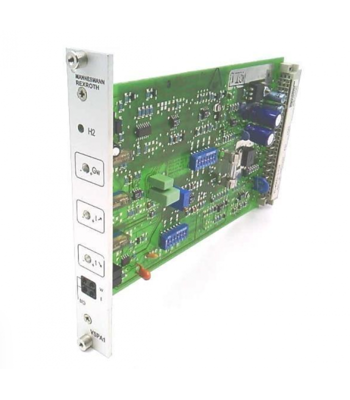
Fig. 1: VT-VSPA1-1-11 Front Panel with Components Labeled
2. Specifications
Electrical Specifications
| Operating Voltage | +24 VDC ± 40% - 5% |
| Input Voltage | Stable voltage +9V for setpoint 1 |
| Input Type | Differential input (±10V), configurable as current input (4-20mA or 0-20mA) |
| Pilot Current | 50mA or 100mA (adjustable) |
| Maximum Output Current | 800mA or 1600mA (configurable) |
| Clock Frequencies | 100Hz, 200Hz, 300Hz, or 370Hz (configurable) |
Environmental & Mechanical
| Operating Temperature Range | -25°C to +70°C |
| Protection Class | IP20 |
| Weight | 0.1 kg |
| Connection Type | 32-pole male multipoint connector and front plate |
| Certifications | CE, UL, RoHS compliant |
3. Installation Guide
3.1 Pre-Installation Preparation
- Verify that the module model VT-VSPA1-1-11 matches the system requirements.
- Inspect the module for any physical damage before installation.
- Ensure the installation environment meets the specified temperature and humidity ranges.
- Prepare the necessary tools: screwdriver, torque wrench, and wire strippers.
- Verify that the power supply is disconnected before starting installation.
3.2 Mounting Procedure
- Hold the controller card by the front panel and remove it from the packaging.
- Slide the controller card into the guard rails of the rack without using excessive force.
- Snap the edge connector in place by gently pressing on the front panel.
- Tighten the two mounting screws on the front panel to secure the module.
3.3 Electrical Connections
- Connect the 24V DC power supply to the appropriate terminals.
- Connect the control signal inputs (4-20mA or ±10V) to the signal terminals.
- Connect the proportional valve solenoid to the output terminals.
- Ensure proper shielding of signal cables to minimize electromagnetic interference.
- Double-check all connections against the wiring diagram before applying power.
WARNING:
Ensure all power is disconnected before making any electrical connections. Improper wiring can cause equipment damage or personal injury.
4. Configuration Instructions
4.1 DIP Switch Settings
The VT-VSPA1-1-11 features DIP switches for configuration of various operating parameters:
| Switch | Function | ON Position | OFF Position |
|---|---|---|---|
| S15-S17 | Valve type selection | Configured for specific valve types | Default valve configuration |
| S21-S22 | Ramp function control | Ramp function enabled | Ramp function disabled |
| S25-S27 | Clock frequency selection | Sets specific frequency (see manual) | Default frequency setting |
| BR22 | Pilot current adjustment | Increases pilot current by 50 or 100mA | Default pilot current setting |
4.2 Potentiometer Adjustments
| Potentiometer | Function | Adjustment Range |
|---|---|---|
| GW | Amplitude attenuator | 0-100% |
| T↑ | Ramp time "ramp up" | 0-5 seconds |
| T↓ | Ramp time "ramp down" | 0-5 seconds |
| ZW/R130 | Pilot current adjustment | 50-100mA |
4.3 Parameter Configuration
- Set the DIP switches according to the valve type and application requirements.
- Adjust the GW potentiometer to set the maximum output amplitude (0-100%).
- Set the T↑ and T↓ potentiometers to configure the ramp times for the output signal.
- Adjust the ZW/R130 potentiometer to set the pilot current (50-100mA).
- Verify all settings against the application requirements before commissioning.
5. Troubleshooting
5.1 LED Indicator Status
| LED | Status | Description | Action |
|---|---|---|---|
| H2 (Green) | Steady ON | Module is powered and operational | Normal operation, no action required |
| H2 (Green) | Flashing | Solenoid conductor cable break or short circuit detected | Check wiring between amplifier and valve |
| H2 (Green) | OFF | No power or internal fault | Check power supply and connections |
5.2 Common Faults and Solutions
| Fault Symptom | Possible Cause | Solution |
|---|---|---|
| No output signal | 1. No power supply 2. Incorrect wiring 3. Internal fault |
1. Check power supply 2. Verify wiring connections 3. Contact technical support |
| Output signal unstable | 1. Loose connections 2. Electromagnetic interference 3. Incorrect parameter settings |
1. Check and tighten connections 2. Improve cable shielding 3. Verify parameter settings |
| Overcurrent fault | 1. Load too large 2. Short circuit in wiring 3. Incorrect parameter settings 4. Mechanical fault in valve |
1. Check load conditions 2. Inspect wiring for short circuits 3. Re-adjust parameters 4. Check valve operation |
| No response to input signal | 1. Incorrect input configuration 2. Input signal out of range 3. Faulty input circuit |
1. Verify input configuration 2. Check input signal levels 3. Test with known good signal |
5.3 Diagnostic Procedures
- Check power supply voltage at the module terminals.
- Verify input signal levels with a multimeter.
- Inspect all wiring connections for tightness and corrosion.
- Check for signs of overheating or damage.
- Verify DIP switch settings against application requirements.
- Measure output current with a clamp meter.
- If problems persist, contact REXROTH technical support with the module serial number and detailed fault description.
6. Interactive Diagram
The following diagram shows the internal structure and signal flow of the VT-VSPA1-1-11 proportional valve amplifier:
Fig. 2: VT-VSPA1-1-11 Internal Structure and Signal Flow
Component Description
Differential Input
Accepts ±10V analog input signals and converts them for processing. Can be configured for 4-20mA current input.
Summing Device
Combines multiple input signals for coordinated control of the valve amplifier.
Amplitude Attenuator
Adjusts the maximum output signal amplitude using the GW potentiometer (0-100%).
Ramp Generator
Controls the rate of change of the output signal using T↑ and T↓ potentiometers (0-5 seconds).
Characteristic Curve Generator
Shapes the output signal according to the selected characteristic curve for optimal valve performance.
Current Controller
Regulates the output current to maintain precise control of the proportional valve solenoid.
Power Output Stage
Provides the necessary power to drive the proportional valve solenoid, up to 1600mA.
Command Value Monitoring
Monitors the command signal to ensure it remains within acceptable limits.
Monitoring Systems
Continuously monitors system parameters and provides fault detection and indication.
Signal Flow Simulation
Click the "Start Simulation" button to visualize the signal flow through the amplifier:
© 2025 Bosch Rexroth AG. All rights reserved.
Technical Documentation for VT-VSPA1-1-11 Proportional Valve Amplifier
Document Revision: 1.0