

HIRSCHMANN MM3-4FXM2 Media Module
- Product Code: MM3-4FXM2
- Availability: In Stock
HIRSCHMANN MM3-4FXM2 Media Module
Technical Documentation
Part Number: 943764101
Table of Contents
1. Product Overview
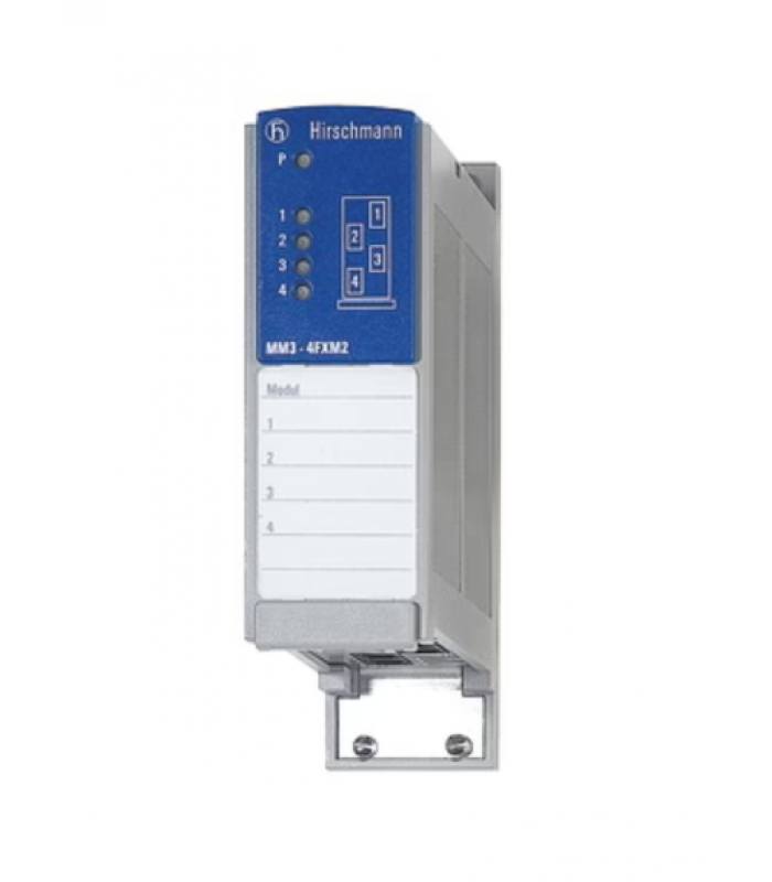
The HIRSCHMANN MM3-4FXM2 is a media module designed for use with MICE series switches (MS20, MS30, and MS4128). This module provides 4 x 100Base-FX ports with multimode fiber optic SC connectors, enabling reliable fiber optic communication in industrial networks.
The MM3-4FXM2 is part of HIRSCHMANN's comprehensive range of industrial networking solutions, specifically engineered to meet the demanding requirements of industrial environments. It offers high reliability, extended temperature range, and robust mechanical design to ensure continuous operation in harsh conditions.
Figure 1: HIRSCHMANN MM3-4FXM2 Front Panel
Key Features
- 4 x 100Base-FX ports with SC connectors
- Support for multimode fiber optic cables
- Extended operating temperature range (0°C to +60°C)
- IP20 protection class
- Hot-swappable design for easy maintenance
- LED indicators for port status monitoring
- High MTBF (Mean Time Between Failures) of 59.5 years
- Robust mechanical design for industrial environments
2. Technical Specifications
| Parameter | Value |
|---|---|
| Part Number | 943764101 |
| Product Name | MM3-4FXM2 |
| Type | Media Module for MICE Switches |
| Ports | 4 x 100Base-FX, SC connectors |
| Data Rate | 100 Mbps |
| Fiber Type | Multimode (MM) |
| Wavelength | 1300 nm |
| Maximum Distance |
|
| Link Budget |
|
| Power Supply | Via backplane of MICE switch |
| Power Consumption | 6.8 W |
| Operating Temperature | 0°C to +60°C |
| Storage/Transport Temperature | -40°C to +70°C |
| Relative Humidity | 10-95% (non-condensing) |
| Dimensions (W x H x D) | 38 mm x 134 mm x 118 mm |
| Weight | 180 g |
| Protection Class | IP20 |
| MTBF | 59.5 years (MIL-HDBK 217F: GB 25°C) |
| Approvals | CE, CUL 508, DNV |
3. Installation Guide
3.1 Safety Precautions
WARNING:
- Always disconnect power before installing or removing modules.
- Use proper ESD (Electrostatic Discharge) protection when handling the module.
- Ensure the switch is properly grounded before installation.
- Do not install the module in an explosive atmosphere or in the presence of flammable gases.
- Ensure proper ventilation and cooling for the switch chassis.
- Follow all local electrical codes and regulations.
3.2 Unpacking and Inspection
Carefully unpack the MM3-4FXM2 module and inspect it for any damage that may have occurred during shipping. The package should contain:
- HIRSCHMANN MM3-4FXM2 media module
- General safety instructions
- Product label sheet (optional accessory)
If any items are missing or damaged, contact your supplier immediately.
3.3 Module Installation
The MM3-4FXM2 module is designed for installation in HIRSCHMANN MICE series switches (MS20, MS30, and MS4128). Follow these steps to install the module:
- Ensure the switch is powered off or the power is disconnected.
- Remove the blank front panel from the switch chassis if present.
- Align the module with the guide rails in the switch chassis.
- Carefully slide the module into the chassis until it makes contact with the backplane connector.
- Secure the module in place using the screws provided (if applicable).
- Repeat steps 2-5 for additional modules if needed.
- Reconnect power to the switch.
Figure 2: HIRSCHMANN MM3-4FXM2 Installation in MICE Switch Chassis
3.4 Fiber Optic Cable Installation
Follow these steps to connect fiber optic cables to the MM3-4FXM2 module:
- Ensure the switch is powered off.
- Remove the dust caps from the SC connectors on the module.
- Remove the dust caps from the fiber optic cables.
- Align the key on the fiber optic connector with the keyway on the module's SC port.
- Insert the connector into the port until it clicks into place.
- Gently pull on the connector to ensure it is securely seated.
- Repeat steps 2-6 for additional fiber optic connections.
- Reconnect power to the switch.
NOTE:
Always use fiber optic cables that meet the specifications for the MM3-4FXM2 module (multimode fiber, 50/125 µm or 62.5/125 µm). Ensure proper handling of fiber optic cables to prevent damage to the fibers.
4. Configuration Instructions
The HIRSCHMANN MM3-4FXM2 module is configured through the management interface of the MICE series switch it is installed in. The configuration options depend on the specific switch model and firmware version.
4.1 Management Options
The MICE series switches can be configured using the following methods:
- Web-based management interface
- Command Line Interface (CLI) via serial port or Telnet/SSH
- SNMP (Simple Network Management Protocol)
- HIRSCHMANN HiVision network management software
4.2 Basic Configuration Steps
To configure the MM3-4FXM2 module, follow these general steps:
- Access the switch management interface using one of the methods listed above.
- Navigate to the port configuration section.
- Select the ports on the MM3-4FXM2 module (typically labeled as ports 5-8 or similar, depending on the switch model).
- Configure the port parameters as required for your network:
- Speed (100 Mbps full duplex for fiber ports)
- VLAN membership
- QoS (Quality of Service) settings
- Link aggregation (if supported)
- Port security settings
- Save the configuration changes.
4.3 Port Configuration Examples
| Configuration Task | Web Interface | CLI Command |
|---|---|---|
| Enable port | Ports → Port Configuration → Select port → Enable | interface [port] no shutdown |
| Set VLAN membership | VLAN → Port VLAN → Select port → Assign VLAN | vlan [id] port member [port] |
| Configure QoS | QoS → Port Priority → Select port → Set priority | interface [port] qos priority [value] |
| Configure port security | Security → Port Security → Select port → Configure settings | interface [port] security mac-address [address] |
NOTE:
For detailed configuration instructions specific to your switch model, refer to the switch's user manual or configuration guide. The exact menu options and CLI commands may vary depending on the switch model and firmware version.
5. Troubleshooting
5.1 LED Indicators
The MM3-4FXM2 module is equipped with LED indicators that provide status information for each port. Refer to the following table to interpret the LED status:
| LED | Color | Status | Description |
|---|---|---|---|
| Link/Act | Green | On | Link is established |
| Link/Act | Green | Blinking | Data is being transmitted/received |
| Link/Act | Off | Off | No link or port is disabled |
| 100M | Green | On | Port is operating at 100 Mbps |
| 100M | Off | Off | Port is not active or not operating at 100 Mbps |
5.2 Common Issues and Solutions
| Issue | Possible Cause | Solution |
|---|---|---|
| No link (Link/Act LED off) | - Fiber optic cable not properly connected - Faulty fiber optic cable - Incorrect fiber type - Port disabled in configuration - Mismatched link partners |
- Check and re-seat fiber connections - Replace fiber optic cable - Verify fiber type (multimode) - Enable port in switch configuration - Verify link partner settings |
| Intermittent link loss | - Loose fiber connections - Damaged fiber cable - Excessive signal loss - Electromagnetic interference - Dirty fiber connectors |
- Secure fiber connections - Inspect and replace damaged cable - Check fiber length and quality - Verify proper grounding and shielding - Clean fiber connectors with appropriate tools |
| Slow network performance | - Bandwidth saturation - Incorrect QoS settings - Duplex mismatch - Network congestion - Faulty module |
- Monitor network traffic - Configure appropriate QoS settings - Verify duplex settings (full duplex recommended) - Implement traffic management - Replace module if necessary |
| Module not recognized by switch | - Module not properly seated - Backplane connector issues - Incompatible switch model - Outdated switch firmware - Faulty module |
- Reinstall the module - Inspect backplane connector - Verify switch compatibility (MS20, MS30, MS4128) - Update switch firmware - Replace module if necessary |
5.3 Fiber Optic Testing
If you suspect issues with the fiber optic link, perform the following tests:
- Visual inspection: Check for visible damage to the fiber cable and connectors.
- Power meter test: Measure the optical power at the receiver end to ensure it is within the acceptable range.
- Optical time-domain reflectometer (OTDR) test: Identify any faults or excessive loss points in the fiber link.
- Loopback test: Connect the transmit and receive ports of the same device using a loopback adapter to verify port functionality.
NOTE:
Fiber optic testing should be performed by qualified personnel using appropriate test equipment.
6. Interactive Module Diagram
The interactive diagram below shows the HIRSCHMANN MM3-4FXM2 media module. Click on the highlighted components to view detailed information about each part of the module.
7. Maintenance
7.1 Regular Maintenance Tasks
| Maintenance Task | Frequency | Procedure |
|---|---|---|
| Visual inspection | Monthly | Check for signs of damage, corrosion, or overheating |
| Cleaning | Quarterly | Clean the module and fiber connectors with appropriate tools |
| Connection check | Semi-annually | Verify all fiber connections are secure |
| Firmware update | As required | Update switch firmware to latest version if necessary |
| Performance monitoring | Continuous | Monitor port status and performance using management tools |
7.2 Module Replacement
To replace the MM3-4FXM2 module, follow these steps:
- Disconnect power from the switch or shut down the switch.
- Disconnect all fiber optic cables from the module.
- Remove the screws securing the module to the chassis (if applicable).
- Carefully slide the module out of the chassis.
- Insert the new module into the chassis as described in the installation section.
- Reconnect the fiber optic cables.
- Reconnect power to the switch or power on the switch.
- Verify proper operation using the LED indicators and management interface.
NOTE:
The MM3-4FXM2 module is hot-swappable in some MICE series switches. Refer to your switch documentation to confirm if hot-swap is supported before attempting to replace the module without powering down the switch.
8. Applications
The HIRSCHMANN MM3-4FXM2 media module is suitable for a wide range of industrial applications that require reliable fiber optic communication:
Industrial Automation
- Factory automation networks
- Process control systems
- Machine vision systems
- Robotics and motion control
Energy Sector
- Power generation plants
- Substation automation
- Distribution automation
- Renewable energy systems
Transportation
- Train control systems
- Traffic management
- Ports and container terminals
- Airport infrastructure
Maritime
- Shipboard networks
- Offshore platforms
- Port automation
- Navigation systems
Building Automation
- HVAC systems
- Security and access control
- Fire safety systems
- Lighting control
9. Technical Support
For technical support, please contact HIRSCHMANN or your local HIRSCHMANN representative:
HIRSCHMANN Headquarters
- HIRSCHMANN Automation and Control GmbH
- Münsterstr. 255
- 47807 Krefeld
- Germany
- Phone: +49 (0) 2151 81-0
- Email: info@hirschmann.com
- Website: www.hirschmann.com
Support Resources
Warranty Information
The HIRSCHMANN MM3-4FXM2 comes with a standard 60-month (5-year) warranty from the date of delivery. For more information on warranty terms and conditions, please refer to the HIRSCHMANN Warranty Policy or contact your local HIRSCHMANN representative.
© 2025 HIRSCHMANN Automation and Control GmbH. All rights reserved.
Document Number: MM3-4FXM2-TD-EN-01
Revision: 1.0