

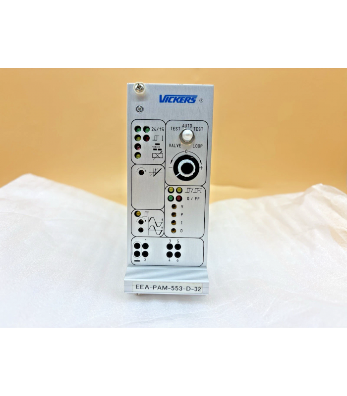
Eaton Vickers EEA-PAM-553-D-32 Proportional Valve Amplifier Module
- Product Code: EEA-PAM-553-D-32
- Availability: In Stock
Eaton Vickers EEA-PAM-553-D-32
Proportional Valve Amplifier Module
1. Product Overview
The Eaton Vickers EEA-PAM-553-D-32 is a sophisticated power amplifier designed to optimize performance and efficiency in hydraulic systems. This digital amplifier provides robust control for hydraulic proportional valves by enhancing system efficiency and response.
- Advanced digital control algorithms for precise and responsive hydraulic system control
- Configurable potentiometers for P-gain, I-gain, and D-gain adjustments
- Integrated PID modules, DIP switches, and potentiometers
- Comprehensive diagnostic features for real-time monitoring and troubleshooting
- Reverse polarity protection and short-circuit protection
2. Technical Specifications
| Parameter | Value |
|---|---|
| Product Type | Power Amplifier Card |
| Series | D-32 |
| Input Voltage | 24V DC |
| Control Voltage | +15V (for LVDTs only) |
| Reference Voltage Outputs | ±10V at 5mA |
| Command Input Voltage Range | ±10V |
| Command Input Impedance | 47 kΩ |
| Current Input Range | 4-20 mA |
| Current Input Impedance | 100 Ω |
| Max. Solenoid Current | 3.2 A |
| Amplifier Input Current (0V command) | 1.7 A |
| Feed-Forward Input Voltage Range | ±10V |
| Feed-Forward Input Impedance | 6 kΩ |
| Ramp Generator Input Impedance | 10 kΩ |
| Ramp-Time Adjustment (minimum) | 50 ms |
| Sensor Input Voltage Range | 0 to ±10V |
| Sensor Input Current Range | 4-20 mA |
| PID Controller Enable Voltage | 17-40V (enabled), 0-3.5V (disabled) |
| PID Controller Current Consumption | <10 mA |
| Output Monitor Point Output | 10 kΩ, short-circuit protected |
| Ramp-Active Indicator Output | 10 kΩ |
| Drive Signal Zero Indicator Output Resistance | 50 Ω |
| Operational Temperature Range | 0°C to 50°C |
| Weight | 330 grams |
3. Connection Diagram & Pin Configuration
Pin Configuration
4. Troubleshooting
When checking the EEA-PAM-553-D-32 amplifier, lights on the front panel will indicate a problem with the system. Use the following troubleshooting guide to identify and resolve common issues.
-
Power Light (Green) Not IlluminatedPossible Causes:
- Insufficient power supply voltage
- Improper or poor electrical connections
- Blown fuse or power supply failure
Remedy:- Check the power supply voltage at the amplifier connections (should be 24V DC)
- Verify wiring continuity and proper pin connections
- Inspect and replace any blown fuses
- Check for short circuits in the power supply线路
-
Fault Light (Red) IlluminatedPossible Causes:
- Power supply voltage below minimum threshold
- Short circuit in output wiring
- Overload condition
- Internal amplifier failure
Remedy:- Check power supply voltage (must be between 17-40V)
- Inspect output wiring for short circuits
- Reduce load on the amplifier
- If problem persists, the amplifier may need replacement
-
No Load MovementPossible Causes:
- Insufficient control pressure or supply pressure
- Improper or poor electrical connections
- Flow ports blocked
- Amplifier or signal source inoperative
- Torque motor inoperative
Remedy:- Check the control pressure or supply pressure
- With the amplifier turned off, check continuity with an ohmmeter for cold solder joints, broken leads, and improper pin wiring
- Check for proper manifolding (O-rings) and for obstructions in hydraulic lines
- Install milliammeters between the torque motor and amplifier to check for proper differential currents
- Check the torque motor coils for open or shorted conditions
-
Load Movement in Only One DirectionPossible Causes:
- One torque motor coil inoperative
- Improper or poor electrical conditions
- Insufficient control pressure
- Flow ports blocked
- Pilot spool not centered
Remedy:- Check the torque motor coils for open or shorted conditions
- Install milliammeters between the torque motor and amplifier to check for proper differential currents
- Check the control pressure
- Check for proper manifolding and obstructions in hydraulic lines
- Re-center pilot spool
-
Erratic Load MovementPossible Causes:
- Amplifier or signal source null shift
- Main sleeve too far out of adjustment
- Contamination in the hydraulic system
- Loose electrical connections
Remedy:- Install milliammeters between the torque motor and amplifier to check for proper differential currents
- Refer to spool centering adjustment procedures
- Install proper filtration and clean system components
- Check and secure all electrical connections
5. Maintenance & Adjustment
Potentiometer Adjustments
The EEA-PAM-553-D-32 amplifier is equipped with configurable potentiometers for adjusting the following parameters:
- P-Gain (Proportional Gain): Adjusts the responsiveness of the system to changes in the error signal
- I-Gain (Integral Gain): Adjusts the system's ability to eliminate steady-state error
- D-Gain (Derivative Gain): Adjusts the system's response to the rate of change of the error signal
- Feed-Forward: Adjusts the feed-forward control signal to improve system response
Zero Adjustment
Located on the amplifier's front face is the zero adjustment. This adjustment should be made if the cylinder is moving with a zero command signal coming into the amplifier. To fix this:
- Ensure the amplifier is receiving a zero command signal
- Rotate the zero adjustment potentiometer until the linear positioner stops drifting
- Verify that the drive signal zero indicator confirms proper zero setting
Regular Maintenance
- Inspect electrical connections quarterly for tightness and corrosion
- Check front panel indicators during system startup to ensure proper operation
- Calibrate amplifier annually or whenever system performance degrades
- Keep the amplifier clean and free from dust and debris
- Ensure proper ventilation around the amplifier to prevent overheating
Always disconnect power before performing any maintenance or adjustments. Use proper electrostatic discharge (ESD) protection when handling the amplifier module.
6. Warranty & Service
The Eaton Vickers EEA-PAM-553-D-32 amplifier is backed by a manufacturer's warranty against defects in materials and workmanship. For specific warranty terms and conditions, please refer to the official Eaton Vickers documentation or contact your local Eaton Vickers representative.
For service and support, contact Eaton Vickers technical support or an authorized service center. Provide the full model number and serial number when requesting assistance.
Warranty coverage may be voided if the amplifier is subjected to improper installation, misuse, neglect, or unauthorized modifications. Always follow the manufacturer's recommended installation and operating procedures.