Low current consumption at and near hydraulic null
Spool is in spring-centered position at loss of power supply: Actuator stops (fail-safe)
Integrated electronics with analog interface
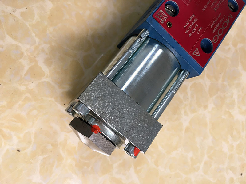
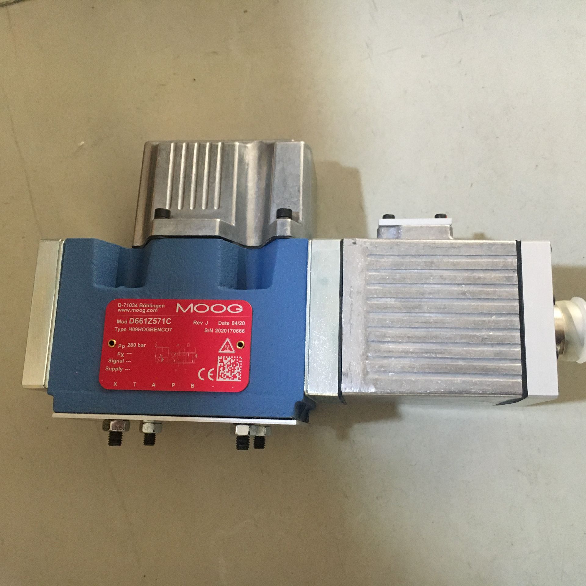
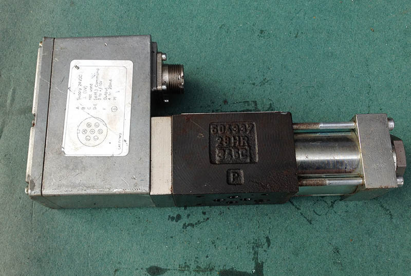
Valve Components
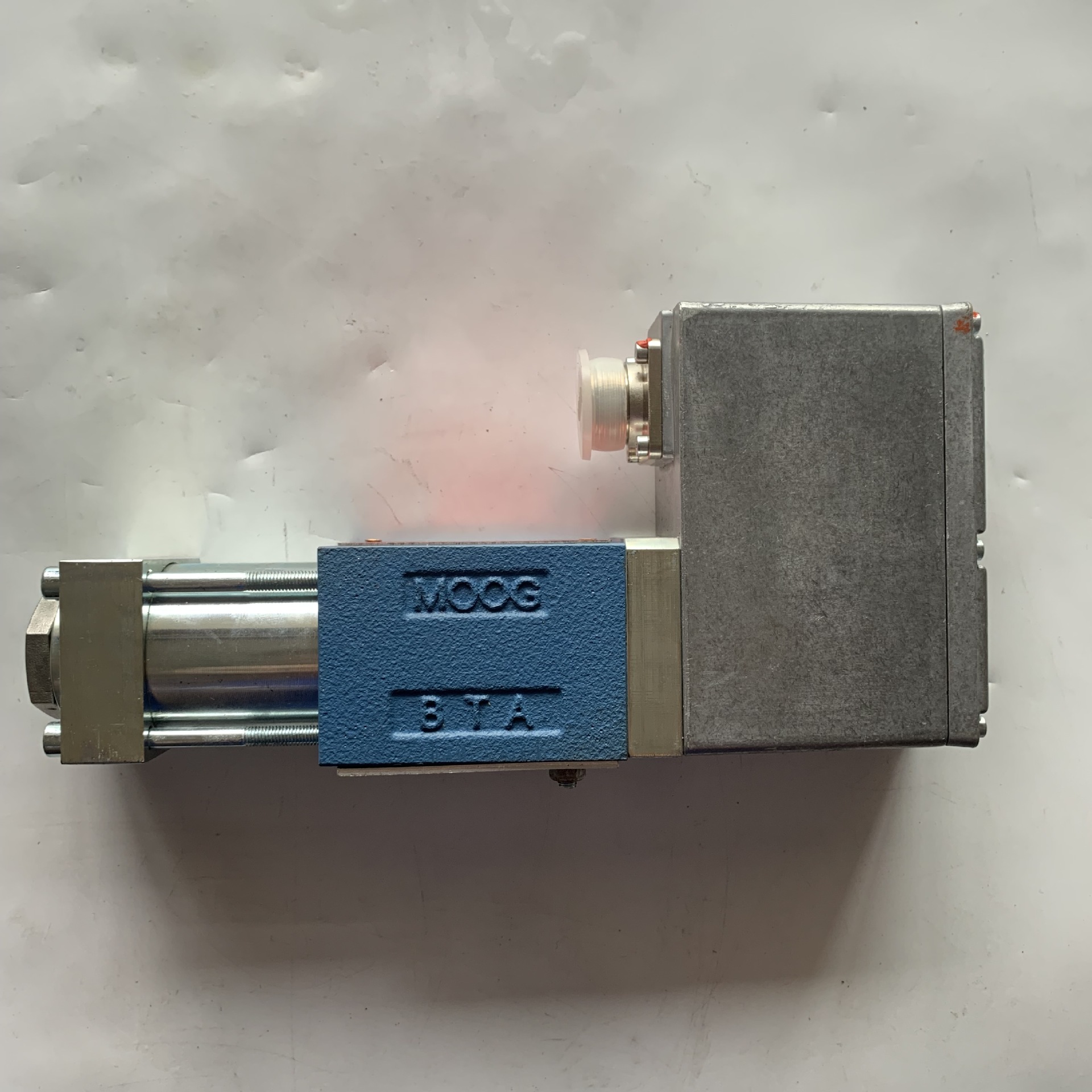
Valve Assembly
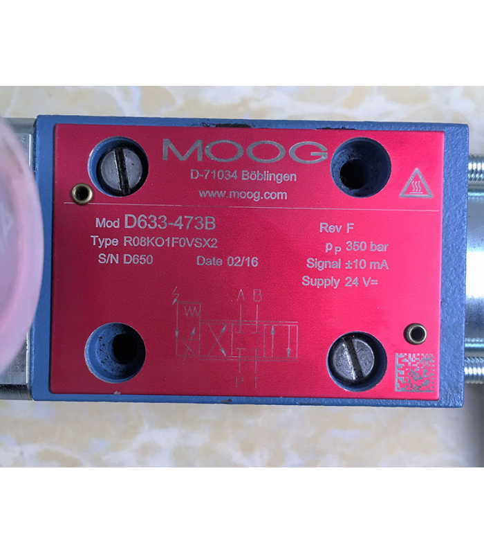
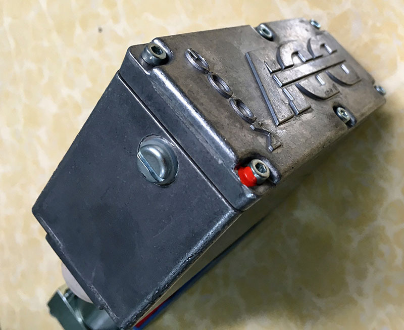
Nameplate Details
Model: D633-473B
Type: R08KO1FOVSX2
Serial Number: D8601
Maximum Pressure: 350 bar
Control Signal: ±10 mA
Supply Voltage: 24 V DC
Interactive Exploded View
Valve Body
Actuator
Electronics Housing
Spool Assembly
Spool Assembly
Linear Motor
Linear Motor
Feedback Sensor
Feedback Sensor
Click on components to view detailed information. Use the controls to explode or reset the view.
Component Details
Maintenance Procedures
Safety Instructions
Before working on the valve, stop the machine and switch off the supply voltage.
Secure the machine against restarting by locking the main command device and removing the key.
Depressurize all hydraulic lines and accumulators before working on the valve.
Wear suitable safety equipment, such as safety shoes, helmet, and work gloves.
Only properly qualified and authorized users may work with and on the valves.
Maintenance Schedule
Maintenance Task
Interval
Description
Hydraulic Fluid Check
Monthly
Check fluid level and condition
Filter Replacement
Every 1000 hours
Replace hydraulic filter cartridge
Oil Analysis
Quarterly
Check oil contamination level (NAS 1638 Class 6 required)
Visual Inspection
Monthly
Check for leaks, damage, and loose connections
Electrical Connection Check
Quarterly
Inspect connectors for corrosion and tightness
Performance Test
Semi-annually
Verify response time and flow characteristics
Maintenance Procedures
Shut down the hydraulic system and relieve all pressure.
Disconnect the electrical power supply to the valve.
Locate the filter housing on the hydraulic circuit near the valve.
Place a container under the filter to catch any spilled fluid.
Unscrew the filter housing using the appropriate wrench.
Remove the old filter element and dispose of it properly.
Clean the filter housing with a lint-free cloth.
Install the new filter element, ensuring proper seating.
Reassemble the filter housing and tighten to the recommended torque.
Refill the hydraulic system with clean fluid if necessary.
Reconnect the electrical power supply.
Start the system and check for leaks.
Note:
Use only genuine MOOG replacement filters to ensure proper performance and avoid damage to the valve.
Ensure the hydraulic system is operational and at normal operating temperature.
Set the input signal to 0 mA (or 0 V) using the control system.
Observe the actuator position or measure the output flow from ports A and B.
If the actuator is not in the neutral position or there is flow from either port, adjustment is needed.
Locate the zero adjustment screw on the valve (typically on the electronics housing).
Loosen the lock nut using a 10 mm wrench.
Use a 3/32 inch hex wrench to turn the adjustment screw:
Clockwise to reduce flow from port A
Counterclockwise to reduce flow from port B
Make small adjustments (1/8 turn or less) and check the response.
Once the valve is properly zeroed (no flow at 0 input signal), tighten the lock nut to 6.5 N·m.
Verify the zero position at several operating pressures to ensure stability.
Note:
Zero adjustment should be performed only when the valve is mounted in the system and under normal operating conditions.
Perform all safety precautions: shut down system, relieve pressure, disconnect power.
Disconnect hydraulic lines from ports P, T, A, and B.
Cap all open hydraulic connections to prevent contamination.
Disconnect electrical connector from the valve.
Remove the valve from its mounting using appropriate tools.
Place the valve on a clean, flat work surface.
Remove the electronics housing by unscrewing the mounting screws.
Carefully lift off the electronics housing, taking care not to damage the internal components.
Disconnect the internal wiring harness from the feedback sensor.
Remove the feedback sensor assembly.
Use a suitable tool to carefully remove the spool assembly from the valve body.
Inspect all components for wear, damage, or contamination.
Clean all components with a suitable solvent and dry with compressed air.
Warning:
Disassembly beyond this point should only be performed by authorized MOOG service personnel. Improper disassembly can cause damage to precision components and void the warranty.
Troubleshooting Guide
Troubleshooting Flowchart
Symptom Occurs
No Response
Check Power Supply
Erratic Operation
Check Signal Quality
Leakage
Inspect Seals & Connections
Common Issues and Solutions
Symptom
Possible Cause
Solution
No response to input signal
Power supply failure
Electrical connector damage
Broken wire
Internal electronics failure
Check power supply voltage
Inspect connector for damage
Check continuity of wires
Contact MOOG service
Erratic or unstable operation
Contaminated hydraulic fluid
Poor electrical connections
Electromagnetic interference
Malfunctioning feedback sensor
Check fluid cleanliness (NAS 1638 Class 6 required)
Clean and secure all connections
Check shielding and grounding
Calibrate or replace feedback sensor
Valve fails to center when de-energized
Broken centering spring
Spool binding
Foreign material in valve
Inspect and replace centering spring
Check for spool binding
Clean valve internals
Excessive leakage
Damaged O-rings or seals
Worn spool or valve body
Loose connections
Replace O-rings and seals
Inspect for wear and replace as needed
Tighten all connections to recommended torque
Reduced performance or response time
Contaminated fluid
Worn components
Incorrect fluid viscosity
Low supply pressure
Change and filter hydraulic fluid
Inspect and replace worn parts
Verify fluid specifications
Check and adjust supply pressure
Diagnostic Tools and Equipment
Recommended Tools
Digital multimeter
Oscilloscope (for signal analysis)
Hydraulic pressure gauge (0-400 bar)
Flow meter
Precision torque wrench
Set of hex wrenches
Filter contamination test kit
Performance Testing
Step response time measurement
Frequency response analysis
Null shift measurement
Flow characteristic verification
Temperature rise testing
Leakage measurement
Installation Instructions
Installation Overview
The MOOG D633-473B servo valve is a direct-operated servo valve with integrated electronics. Proper installation is critical to ensure optimal performance and longevity.
Important Note
The valve can be mounted in any orientation, either fixed or movable. However, the mounting surface must meet specific flatness requirements.
Installation Steps
1. Preparation
Verify that the valve model and part number match the requirements
Inspect the valve for any damage that may have occurred during shipping
Check that all necessary mounting hardware is available
Ensure the hydraulic fluid meets the required specifications