

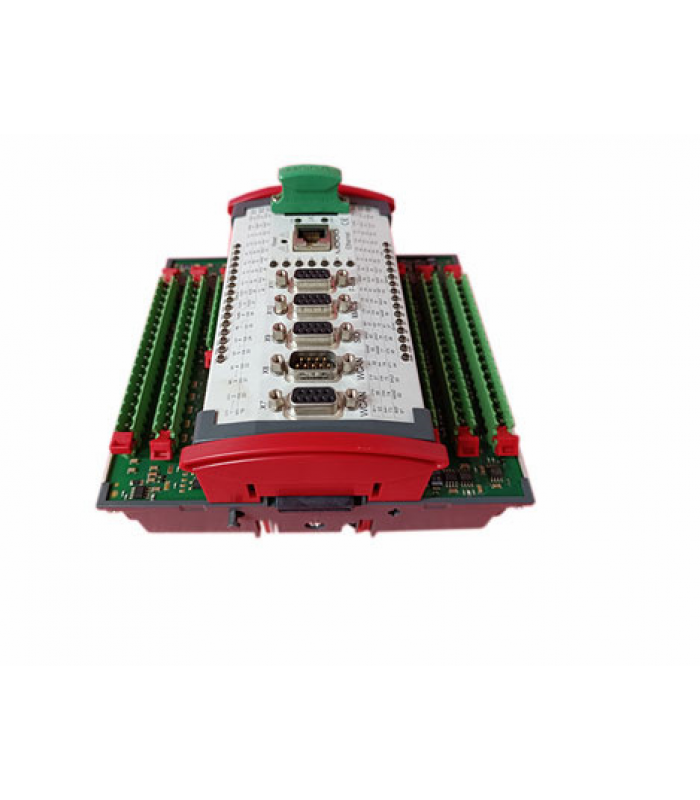
MOOG D136-002-005 Hydraulic Servo Valve
- Product Code: D136-002-005
- Availability: In Stock
MOOG D136-002-005 Technical Specification Sheet
Hydraulic Servo Valve | Industrial Grade | Revision: A (2025)
1. Product Overview
The MOOG D136-002-005 is a high-performance proportional hydraulic servo valve designed for industrial motion control applications. Engineered with MOOG’s proprietary feedback technology, this component delivers precise flow control, rapid response times, and exceptional durability in harsh operating environments (e.g., manufacturing, aerospace testing, and heavy machinery).
Key design features include a stainless steel valve body, corrosion-resistant internals, and a compact form factor for seamless integration into existing hydraulic systems.
2. Technical Specifications
| Parameter | Value | Unit |
|---|---|---|
| Maximum Supply Pressure | 350 | bar (MPa: 35) |
| Nominal Flow Rate (at 70 bar) | 25 | L/min |
| Operating Temperature Range | -20 to +80 | °C |
| Electrical Input Signal | 4-20 | mA (DC) |
| Response Time (10-90%) | < 10 | ms |
| Weight | 1.8 | kg |
3. Installation Guidelines
- Mount the valve in a vibration-dampened location to prevent mechanical stress on the valve body and electrical connectors.
- Ensure hydraulic lines are flushed and free of contaminants (ISO 4406 Class 18/15) before connection to avoid internal component damage.
- Connect the electrical signal cable to the DIN 43650 A connector (IP65 rated) and secure with a strain relief to prevent cable pull-out.
- Align the valve’s port markings (P = Supply, T = Tank, A/B = Work Ports) with the hydraulic system’s corresponding lines.
- Torque all hydraulic fittings to MOOG-recommended values (refer to MOOG Hydraulic Fitting Torque Chart (PN: 987-001)).
4. Maintenance & Troubleshooting
Preventive Maintenance
Perform quarterly inspections of hydraulic fluid quality and replace the system filter (10 μm) every 2,000 operating hours. Inspect electrical connections for corrosion and tightness semi-annually.
Common Issues & Resolutions
Issue 1: No flow response to electrical signal → Check input signal integrity (4-20 mA) and verify power supply to the valve coil; replace the coil if open-circuited.
Issue 2: Erratic flow control → Inspect hydraulic fluid for contamination; flush the system and replace the valve’s internal spool if worn.
Issue 3: Leakage at ports → Retorque fittings to specification or replace damaged O-rings (MOOG PN: 123-004-001).
5. Safety Information
WARNING: De-energize the hydraulic system and relieve all pressure before performing installation, maintenance, or repair work to avoid serious injury from pressurized fluid ejection.
This component must be installed and serviced by qualified personnel trained in hydraulic systems and MOOG product procedures. Refer to the full MOOG D136 Series Safety Manual (PN: D136-000-001) for additional safety precautions.
MOOG Inc. | 1000 MOOG Drive, East Aurora, NY 14052, USA | Tel: +1 (716) 652-2000 | www.moog.com
Document ID: DOC-D136-002-005 | Last Updated: November 2025