


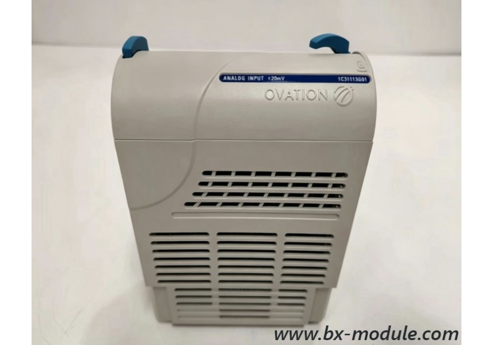
Ovation DCS Emerson Analog Input Module Configuration Tutorial
Ovation DCS Emerson Analog Input Module Configuration Tutorial
This complete tutorial covers the full setup, wiring, parameter tuning, fault diagnosis and commissioning steps for Emerson Ovation DCS analog input modules, applicable to industrial power plants, petrochemical and gas processing monitoring control systems. All operations match official Ovation engineering workstation software standards.
1. Overview of Ovation Analog Input Module Series
- 1C31113G01 Standard 8-channel Analog Input Card (4-20mA signal)
- 1C31116G01 Thermocouple & RTD Temperature Input Module
- 1C31234G01 High Precision Low Level Analog Input Board
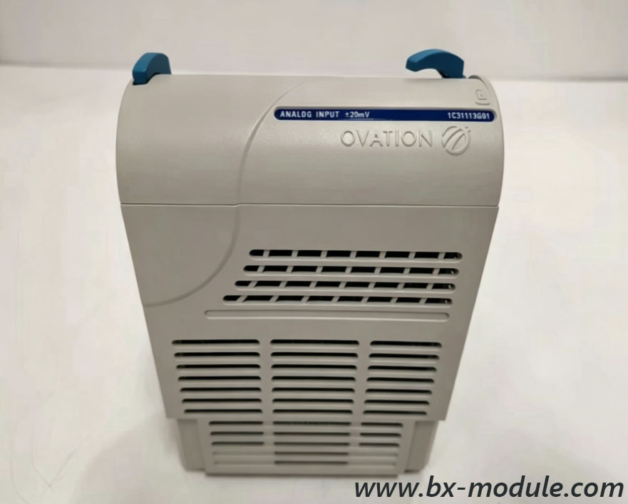
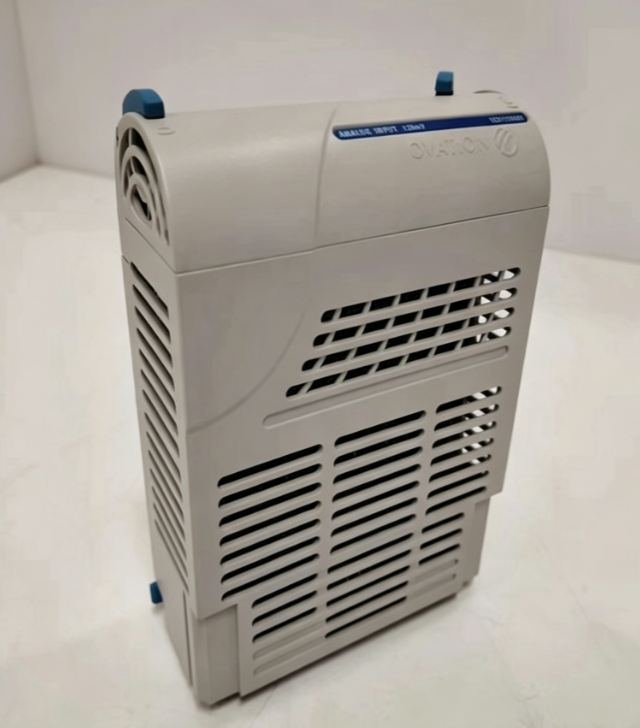
- 5X00121G01 Isolated 16-channel Analog Input Module
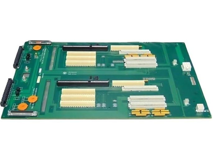
- Ovation I/O Rack Backplane & Power Matching Accessories
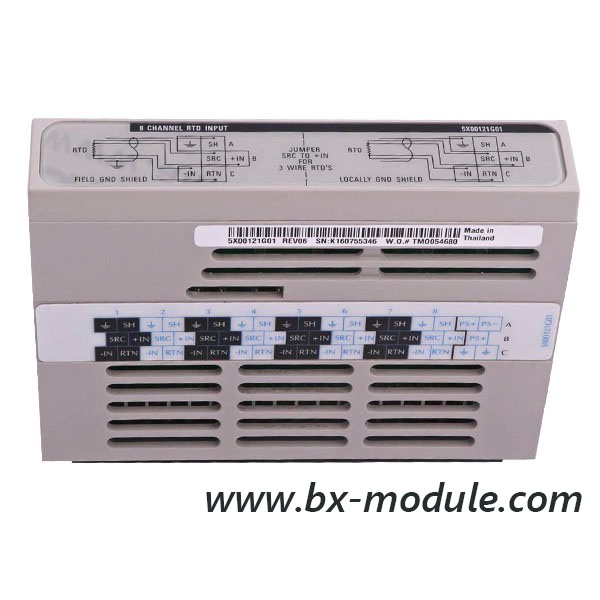
Main supported signals: 4–20mA current loop, 0–10V voltage, PT100 RTD, K/T/E/J type thermocouple, resistance temperature signals for boiler, turbine and auxiliary equipment measurement.
2. Pre-Configuration Preparation Checklist
- Confirm physical installation: Module fully inserted into Ovation I/O rack, rack power supply normal, backplane contact intact.
- Prepare engineering workstation with Ovation Developer Studio software and administrator access permission.
- Collect field sensor parameters: measuring range, signal type, sensor offset, engineering unit (bar, ℃, m³/h, MW).
- Complete field wiring: Shielded cable connection, positive/negative polarity verification, grounding treatment to eliminate signal interference.
- Prepare multimeter for post-configuration signal calibration and loop testing.
3. Hardware Wiring & Ground Specification
3.1 4-20mA Two-Wire Transmitter Wiring
Connect module channel positive terminal to transmitter power positive, channel negative terminal return to transmitter negative; install signal shield single-point grounding at I/O cabinet side only, avoid double grounding loop current noise.
3.2 RTD/Thermocouple Temperature Sensor Wiring
3-wire PT100 requires equal-length three shielded wires to reduce line resistance error; thermocouple signal cables must use dedicated compensation wire matched with thermocouple grade to prevent cold junction drift.
3.3 Anti-interference Requirements
Analog signal cables shall be separated from high-voltage motor power cables by at least 30cm; all cable shielding ends connect to cabinet ground copper bar.
4. Step-by-Step Software Configuration on Ovation Developer Studio
Step 1: Create I/O Node & Scan Rack Definition
Log into Ovation Developer Studio, open the target control controller project. Navigate to I/O Hardware Manager, create new I/O node matching the physical rack address, set rack slot number corresponding to analog input module position.
Step 2: Import Correct Analog Input Module Model
Select the exact part number of the installed AI module from the Emerson hardware library. Enable hardware detection function to auto-verify module online status, resolve mismatch alarm if model error occurs.
Step 3: Single Channel Signal Parameter Setup
- Signal Type: Select 4-20mA, RTD, TC, or DC Voltage per field device
- Raw Scale: Set minimum raw value (4mA=0 count) and maximum raw value (20mA=4000 count)
- Engineering Scale: Map raw signal to actual process range (e.g. 0–100 ton/h, 0–500℃)
- Engineering Unit: Input unit label for HMI display and historical trend storage
- Filter Time Constant: Adjust digital filter to suppress high-frequency signal fluctuation (default 200ms)
- Channel Alarm Threshold: Configure high-high, high, low, low-low process alarms
- Break Detection: Activate wire break alarm for open circuit transmitter cable failure
Step 4: Point Database Creation & HMI Binding
Generate AI point tags automatically for each channel, fill point description, equipment tag number, equipment area classification. Link configured point tags to graphic display screens, real-time trend windows and historical log archives for operator monitoring.
Step 5: Download Configuration to Ovation Controller
Compile all I/O configuration files without syntax error, perform hot download to target redundant controller pair. Confirm download completion status, refresh I/O hardware online monitoring panel to view real-time channel signal values.
5. Loop Calibration & Commissioning Test
- Use signal generator to inject 4mA, 12mA, 20mA standard signals into each analog channel.
- Compare DCS HMI display value against generator standard value, record measurement deviation.
- Tune channel linear correction factor if deviation exceeds allowable tolerance (±0.5% FS).
- Simulate wire break condition to verify break detection alarm pops up correctly on operator screen.
- Check redundant controller switching function to ensure analog signal data remains stable during master/backup switchover.
6. Common Configuration Faults & Troubleshooting
- No channel reading / full scale fixed value: Wrong wiring polarity, broken shield cable, module slot address configuration mismatch
- Severe signal jumping fluctuation: Poor single-point grounding, high voltage cable crosstalk, filter time constant set too small
- Wire break alarm false triggering: Transmitter internal resistance drift, loose terminal block wiring
- Module offline hardware alarm: Loose module insertion, rack power supply undervoltage, backplane damaged channel slot
- Linear measurement error out of tolerance: Incorrect engineering scale setup, uncalibrated field transmitter
Post-Configuration Operation Standard
After successful commissioning, save full project backup file, print I/O channel parameter record sheet for maintenance archive. Set regular monthly signal calibration cycle for critical process analog input modules to guarantee long-term Ovation DCS measurement accuracy and system stable operation.