

Yokogawa ZR402G-M-E-E-A Separate Type Zirconia Oxygen Analyzer
- Product Code: ZR402G-M-E-E-A
- Availability: In Stock
Yokogawa ZR402G-M-E-E-A
Separate Type Zirconia Oxygen Analyzer
Product Overview
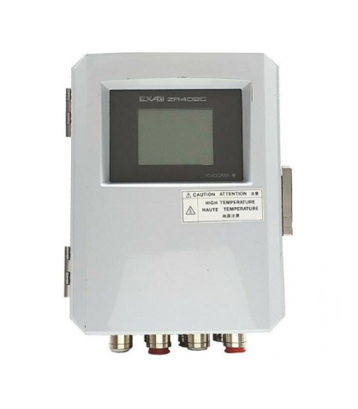
The Yokogawa ZR402G-M-E-E-A is a high-performance separate type zirconia oxygen analyzer designed for combustion monitoring and control in various industrial applications. It features a user-friendly LCD touch screen interface and incorporates advanced zirconia sensor technology for accurate and reliable oxygen concentration measurement.
This analyzer system helps industries achieve energy savings and reduce environmental impact by enabling more complete combustion, thus lowering CO₂, SOₓ, and NOₓ emissions. It is suitable for use in iron and steel, electric power, oil and petrochemical, ceramics, pulp and paper, food, textile industries, and various combustion facilities.
Key Features
- LCD touch screen interface
- High-reliability zirconia sensor
- Field-replaceable heater assembly
- HART communication for remote maintenance
Applications
- Boiler combustion control
- Industrial furnace efficiency monitoring
- Incinerator emissions control
- Process gas analysis

Technical Specifications
| Parameter | Value |
|---|---|
| Model Number | ZR402G-M-E-E-A |
| Measurement System | Zirconium oxide sensor |
| Measurement Object | Oxygen concentration in combustion exhaust gas and mixed gas |
| Measurement Range | 0.01 to 100 vol% O₂ |
| Setting Range | Any setting from 0-5 vol% O₂ to 0-100 vol% O₂ (in 1 vol% O₂ increments) |
| Output Signal | 4 to 20 mA DC, two points (maximum load resistance 550 Ω) |
| Contact Output | Four points (one is fail-safe, normally open) |
| Contact Input | Two points |
| Analog Input | One point (thermal input 4-20 mA) |
| Digital Communication | HART (250 to 550 Ω loop resistance) |
| Sample Gas Pressure | -5 to +250 kPa (pressure compensation required over +5 kPa) |
| Sample Gas Temperature | 0 to 700°C (probe only) |
| Calibration Method | Zero/span calibration (automatic, semi-automatic, and manual) |
Mechanical Properties
Dimensions
22.80 cm x 13.63 cm x 28 cm (L x W x H)
Weight
Approximately 6 kg
Construction
Case: Aluminum alloy
Finish: Polyurethane corrosion-resistance coating
Color
Silver gray (Munsell 3.2PB 7.4/1.2)
Wiring Connection
G 1/2, PG 13.5, M20 × 1.5, 1/2 NPT (with plug), eight holes
Installation
Panel, wall or pipe mounting
Environmental Conditions
Temperature Range
Operating: -20°C to +55°C
Storage: -30°C to +70°C
Humidity
0 to 95% RH (non-condensing)
Power Supply
Voltage: 100 to 240 V AC (85 to 264 V AC acceptable)
Frequency: 50/60 Hz (45 to 66 Hz acceptable)
Power Consumption: Max. 300 W, approx. 100 W for ordinary use
Environmental Rating
Suitable for industrial environments
Protection against dust and water splashes
Features and Benefits
LCD Touch Screen Interface
The ZR402G incorporates a 320 x 240 dot LCD touch screen for easy operation. It provides various setting displays, oxygen concentration trend display, and calibration displays, making operation intuitive and efficient.
Field-Replaceable Components
The built-in heater assembly of the probe can be replaced on site, reducing maintenance costs and downtime. The probe uses a long-life, high-reliability, field-replaceable zirconia sensor.
HART Communication
Remote maintenance using digital communications (HART) reduces maintenance costs. This allows for remote monitoring, configuration, and diagnostics, minimizing the need for on-site visits.
Comprehensive Self-Diagnostics
The analyzer is equipped with various standard functions such as measurement and calculation as well as maintenance functions including self-test. Error messages display not just error numbers but also descriptions for easy troubleshooting.
Flexible Calibration Options
The ZR402G supports automatic, semi-automatic, and manual calibration modes. An optional automatic calibration unit (ZR40H) is available for fully automated calibration procedures.
User-Friendly Design
The conversational interface allows easy operation by following on-screen instructions. Various display modes including setting screens, oxygen concentration trend screens, and calibration operation displays make configuration accessible to all users.
Applications
Industrial Furnaces
Used in refinery processes, iron manufacturing heating furnaces, coal kilns, and black liquid recovery boilers for combustion efficiency monitoring and control.
Boilers
Ideal for large, medium, and small boilers (power generation boilers using heavy oil, gas, or coal) to optimize combustion efficiency and reduce emissions.
Incinerators
Used in various waste incineration facilities to monitor and control combustion processes, ensuring complete combustion and minimizing harmful emissions.
Food Industry
Applied in food processing facilities for controlled atmosphere processes, ensuring product quality and safety.
Textile Industry
Used in textile manufacturing processes, particularly in coloring and drying operations requiring precise oxygen control.
Pulp and Paper Industry
Applied in pulp manufacturing and paper drying processes to optimize energy usage and product quality.
Installation Guidelines
Choose a suitable location for installation (panel, wall, or pipe mounting).
Ensure the ambient temperature is within the specified range (-20°C to +55°C).
Provide proper ventilation for heat dissipation.
Follow the wiring diagram for proper electrical connections.
Ensure proper grounding for electromagnetic compatibility.
Mount the detector at the appropriate position in the flue or process line.
Connect the detector to the converter using the specified cables.
Perform initial calibration before putting the analyzer into service.
Important: Follow all safety guidelines and local regulations during installation. Ensure the power supply is disconnected before making any electrical connections.
Maintenance Procedures
Regular Maintenance
- Daily: Check display readings and status indicators
- Weekly: Verify calibration and perform span check
- Monthly: Clean the detector and check cable connections
- Quarterly: Perform complete calibration and function test
- Annually: Replace heater assembly and check sensor condition
Calibration Procedure
- Access the calibration menu via the touch screen interface
- Select the appropriate calibration mode (automatic, semi-automatic, or manual)
- Follow the on-screen instructions for zero calibration
- Perform span calibration using a known gas mixture
- Verify calibration results and adjust if necessary
- Save calibration data and exit the calibration menu
Sensor Replacement
- Turn off the power supply to the analyzer
- Disconnect the detector from the process line
- Remove the old sensor from the detector housing
- Install the new sensor and ensure proper seating
- Reconnect the detector to the process line
- Reconnect power and perform initial calibration
Troubleshooting Tips
- Refer to the error message display for specific fault information
- Check power supply and cable connections for loose or damaged wires
- Verify detector installation and process conditions
- Perform a function test using the built-in self-test feature
- Contact Yokogawa technical support for complex issues
Performance Characteristics
Ordering Information
Model Code Explanation
ZR402G-M-E-E-A
Accessories and Options
ZR40H
Automatic calibration unit
ZR22G
Standard detector (various lengths)
ZR22S
Explosion-proof detector
ZR22P
High-temperature probe adapter
Disclaimer
Yokogawa Electric Corporation reserves the right to modify the specifications contained herein without prior notice. The information provided in this document is believed to be accurate and reliable, but Yokogawa assumes no responsibility for any errors or omissions.
This product is designed for industrial use only. Any use outside of industrial environments may result in product damage or personal injury.
For the latest product information, technical documentation, and support, please visit the Yokogawa website at www.yokogawa.com.
© 2025 Yokogawa Electric Corporation. All rights reserved.